0%

As electricity systems become more digital, a short transfer delay can stop a production line, server rack, or medical device. The International Energy Agency’s Electricity 2024 report projects global electricity demand growth of about 4% in 2024 and 2025. More demand increases pressure on continuity planning, not merely on generation capacity. Uptime Institute’s Annual Outage Analysis 2024 continues to identify power problems as a leading cause of serious data-center outages. That finding matters beyond data centers. It reveals the quiet weakness between two available sources. The details matter.

A Dual Power Automatic Transfer Switch monitors two incoming supplies and moves the load when voltage, frequency, or phase conditions fail. Choosing one is not a catalog exercise. Engineers should verify rated current, short-circuit withstand, transfer time, neutral switching, bypass isolation, controller alarms, and maintenance access. IEC 60947-6-1 provides a useful reference for transfer-switch equipment, while local installation rules govern the final design. In a factory, imagine a 400 A feeder, a warm enclosure, dust near the terminals, and a generator starting under load. Those conditions can change the preferred model.

This guide connects published evidence with practical selection experience. It examines source priorities, load categories, switching mechanisms, protection coordination, and testing routines. A neat specification can still fail during maintenance. No switch is perfect. I would not treat every market figure as universal, because site conditions and operating practices vary widely. Reliable selection therefore requires more than comparing prices or advertised transfer times. It requires measured data, qualified engineering review, documented commissioning, and realistic failure testing. The strongest decision is usually the one that remains understandable during an alarm at 2 a.m.
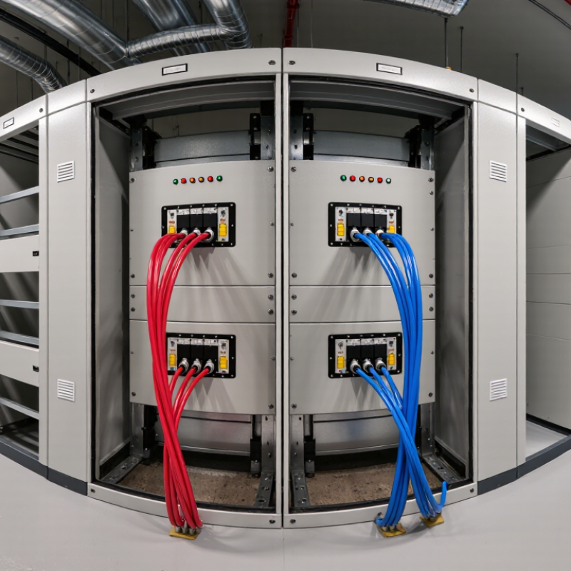
How to Choose a Dual Power Automatic Transfer Switch?

Define Dual-Power ATS Types, Transfer Modes, and IEC 60947-6-1 Standards

How to Choose a Dual Power Automatic Transfer Switch?

A dual-power ATS connects a critical load to two independent sources. The sources may be utility feeders, generators, or a utility-generator combination. Choose the source arrangement after checking voltage, frequency, phase sequence, neutral switching, and available short-circuit current. The International Energy Agency’s Electricity 2024 report expects global electricity demand to grow by about 3.4% annually from 2024 to 2026. More demand increases pressure on supply continuity.

Type matters. IEC 60947-6-1:2021 covers transfer switching equipment, including construction, performance, temperature-rise, dielectric, and short-circuit tests. A PC-class ATS uses mechanically interlocked switching devices. A CB-class design uses circuit breakers and may offer stronger protection coordination. Check the rated operational current, utilization category, poles, and short-time withstand rating. Do not select by amperage alone.

Transfer mode changes the load experience. Open transition uses break-before-make switching and prevents both sources from connecting simultaneously. Closed transition briefly parallels sources, so synchronization and utility approval may be necessary. Delayed transition holds the load disconnected, helping discharge motors and residual voltage. The Uptime Institute’s 2024 Global Data Center Survey continues to identify power events as a major outage concern, but an ATS cannot correct poor maintenance or unstable generators. Field testing matters. A neat spreadsheet can still miss neutral displacement, generator warm-up time, or a failed position sensor. Specify alarm contacts, manual bypass, event logging, and monthly functional tests. Both sources matter.

Match Load Ratings, AC-33B Categories, and Short-Circuit Withstand Values

How to Choose a Dual Power Automatic Transfer Switch?

A dual power automatic transfer switch must match the real load, not only the nameplate current. Check continuous amperage, motor starting current, voltage, frequency, and neutral arrangements. AC-33B matters when the circuit combines motors, compressors, transformers, and resistive loads. It reflects demanding switching conditions under IEC 60947-6-1 test requirements. A unit rated for simple resistive loads may fail during a pump restart. That mistake is common.

Short-circuit data deserves equal attention. Compare the installation’s prospective fault current with the switch’s rated short-time withstand current, Icw, and making capacity, Icm. Also verify the conditional short-circuit rating with the specified protective device. These values are not interchangeable. A higher ampere rating does not automatically mean stronger fault performance. Ask for test certificates and coordination tables. Numbers without test conditions can mislead.

The IEA Electricity 2024 report estimates that data centres consumed about 460 TWh globally in 2022, with demand potentially exceeding 1,000 TWh by 2026. Uptime Institute’s 2023 Annual Outage Analysis reported that 55% of respondents experienced outage costs above 100,000 dollars. That context makes conservative selection sensible. Still, oversizing everything wastes money and can reduce measurement accuracy. I have seen specifications copied from older projects. They looked professional, but the available fault current had changed. Recheck the site study, cable length, protection settings, and actual motor duty before approval.

How to Choose a Dual Power Automatic Transfer Switch? - Match Load Ratings, AC-33B Categories, and Short-Circuit Withstand Values
Application Example System Voltage Estimated Active Load Assumed Power Factor Calculated Three-Phase Current Recommended ATS Rating Required Utilization Category Suggested Pole Configuration Prospective Short-Circuit Current at Installation Point Minimum Target Icw
(1 Second)
Selection Comment
Small commercial building or control panel 400 V AC, 3-phase, 50 Hz 30 kW 0.85 50.9 A 63 A AC-33B 4-pole when neutral switching is required; otherwise 3-pole 8 kA RMS 10 kA RMS Provides a practical rating margin above the calculated operating current. Confirm that the upstream protective device limits the available fault current.
Office floor, retail unit, or light industrial distribution board 400 V AC, 3-phase, 50 Hz 55 kW 0.85 93.4 A 100 A AC-33B 4-pole for switched neutral systems 12 kA RMS 15 kA RMS Use the AC-33B current rating rather than an AC-31 rating when motors, transformers, or mixed inductive loads are transferred.
Medium commercial facility or pump control system 400 V AC, 3-phase, 50 Hz 90 kW 0.85 152.8 A 160 A AC-33B 4-pole where the neutral must be isolated between sources 20 kA RMS 25 kA RMS Check motor starting current, generator transient voltage, and the ATS making capacity before final approval.
Large building services or multiple motor feeders 400 V AC, 3-phase, 50 Hz 150 kW 0.85 254.7 A 320 A AC-33B 4-pole if required by the earthing and neutral arrangement 30 kA RMS 35 kA RMS A 250 A switch would not provide sufficient continuous-current margin for this calculated load. Verify busbar temperature-rise and cable termination limits.
Critical facility main transfer or high-capacity generator supply 400 V AC, 3-phase, 50 Hz 250 kW 0.85 424.5 A 500 A AC-33B 4-pole when source neutral isolation is part of the design 42 kA RMS 50 kA RMS Use a tested combination of ATS, upstream protective device, and enclosure. Confirm the assembly short-circuit rating at the actual installation voltage.
Current calculation: For a balanced three-phase load, the estimated line current is calculated as I = P ÷ (√3 × V × power factor). The examples use 400 V AC and a 0.85 power factor. Actual design current must include continuous-load requirements, motor starting conditions, harmonics, ambient temperature, and future expansion.
Selection checklist: Choose an ATS with an AC-33B utilization category when the transferred load includes motors or mixed resistive and inductive equipment. Match the rated operational current to the load, select the correct number of poles for the neutral and earthing system, and ensure that the declared short-circuit withstand value is equal to or greater than the calculated prospective fault current. Icw is a withstand rating for a specified duration; it must not be treated as a universal substitute for the complete short-circuit rating of the installed assembly.

Select Transfer Times from Milliseconds to Seconds for Critical Loads

How to Choose a Dual Power Automatic Transfer Switch?

Select transfer times from milliseconds to seconds according to the load, not marketing claims. A medical imaging system, server rack, or industrial controller may reset during a brief interruption. Static transfer equipment can switch in approximately 2–6 milliseconds under suitable conditions. Electromechanical transfer switches commonly require 50–300 milliseconds. Exact timing depends on sensing, source stability, contact movement, and load characteristics. Request test records, not only catalog figures.

Uptime Institute’s 2023 Annual Outage Analysis reported that 60% of impactful outages exceeded $100,000 in cost. Ponemon Institute also estimated the average data-center outage cost at $740,357 in its 2016 study. These figures explain why a slower, carefully coordinated transfer can be safer than an ultra-fast switch. Confirm phase matching, voltage tolerance, frequency limits, and generator stabilization time. A UPS may bridge milliseconds, while an ATS waits seconds for reliable standby power. It is easy to overlook this coordination.

IEC 60947-6-1 provides a useful reference for transfer-switch performance and safety. During commissioning, measure actual transfer time with a power-quality analyzer. Simulate source failure, recovery, overload, and neutral switching. Keep records.

The neatest specification can still fail.

A practical weakness is assuming every critical load needs millisecond transfer. Some loads tolerate several seconds, while others require continuous conditioning. Review the equipment’s ride-through data, then select the fastest dependable arrangement that avoids nuisance transfers and unstable generator operation.

Verify Pole Configuration, Voltage, Frequency, and Phase Compatibility

How to Choose a Dual Power Automatic Transfer Switch?

A dual power automatic transfer switch must match the installation, not just the load rating. Verify the pole configuration first. A three-pole switch may leave the neutral unswitched. A four-pole model switches neutral conductors, which can matter in separately derived systems. Confirm this choice with the site’s grounding design and a qualified electrician.

Check voltage, frequency, and phase compatibility on both power sources. A 400 V, 50 Hz system cannot automatically accept a 480 V, 60 Hz source. Confirm whether the supply is single-phase or three-phase. Then compare phase sequence, line-to-line voltage, and control voltage. IEC 60947-6-1 provides requirements for transfer switching equipment. The Uptime Institute’s 2024 Annual Outage Analysis reported that over half of surveyed outages created financial impacts above $100,000. Incorrect source matching can turn a short transfer into costly downtime. That risk deserves careful testing.

Tips: Read the nameplate. Measure voltage. Check frequency. Count poles. Test phase rotation. Review neutral switching. Record findings before ordering. I often recheck phase sequence after maintenance, because field labels can be misleading. A small assumption can create a serious fault. Select equipment with suitable short-circuit ratings, transition time, and switching capacity. Do not rely only on nominal voltage. Verify actual site readings under normal and standby conditions.

Compare Controller Features, Bypass Options, Testing, and Maintenance Needs

How to Choose a Dual Power Automatic Transfer Switch?

A dual power automatic transfer switch should match the facility’s real load profile, not only its rated current. During commissioning, check controller features such as adjustable transfer delays, phase-loss detection, undervoltage sensing, and event logging. A clear screen helps technicians trace a failed transfer beside a noisy generator room. Remote alarms are useful, but they should not replace local indicators. The controller should also support closed-transition or delayed-transition modes when the application requires them. IEC 60947-6-1 provides a relevant performance framework for transfer switching equipment.

Bypass options deserve careful attention. A maintenance bypass can keep critical loads energized while technicians isolate the main switching mechanism. Verify mechanical interlocking, source isolation, and the permitted switching sequence. A bypass that looks convenient may introduce operator error. Testing should include simulated source failure, return-to-normal timing, phase rotation, and manual operation. The 2024 Uptime Institute Annual Outage Analysis reported that 54% of respondents experienced an outage costing more than $100,000. That figure makes routine testing difficult to dismiss. Still, testing plans are often too optimistic. Real maintenance records reveal missed intervals.

Tips: Ask for factory test records and site acceptance results. Align inspection intervals with NFPA 110, NETA testing guidance, and the equipment’s duty cycle. Record contact wear, terminal torque, battery condition, and transfer counts. Keep spare control fuses available. Do not test during peak production without a documented contingency plan.

How to Choose a Dual Power Automatic Transfer Switch?

Compare controller features, bypass options, testing, and maintenance needs

The chart shows the maximum transfer-time classifications commonly used for emergency power systems under NFPA 110. When selecting a dual-power automatic transfer switch, confirm that the controller supports source-voltage and frequency monitoring, adjustable transfer delays, event logging, and manual or automatic testing. A bypass-isolation option is useful when the switch must be inspected or serviced without interrupting the load. Testing intervals and maintenance procedures should follow the applicable electrical code, site risk assessment, and the equipment manufacturer's instructions.

Reference: NFPA 110 emergency power-system performance classifications. Verify the applicable edition and local requirements before specifying equipment.

FAQS

What load information should be checked before selecting a dual power automatic transfer switch?

Check continuous current, motor starting current, voltage, frequency, and neutral arrangement. The nameplate is not enough. Pump restarts can create sharp current peaks.

What does the AC-33B category indicate?

AC-33B covers demanding loads, including motors, compressors, transformers, and resistive equipment. It reflects difficult switching conditions. A resistive-load rating may fail during motor restarting.

Why is a higher ampere rating not always safer?

Ampere capacity does not automatically indicate short-circuit strength. Compare prospective fault current with Icw and Icm values. Numbers need test conditions.

What short-circuit information should be requested?

Request rated short-time withstand current, making capacity, and conditional short-circuit ratings. Confirm the specified protective device. Ask for test certificates and coordination tables.

Which controller features are useful during commissioning?

Adjustable transfer delays, phase-loss detection, undervoltage sensing, and event logging are valuable. A clear display helps technicians trace failures. Local indicators still matter.

When is a maintenance bypass useful?

A maintenance bypass can keep critical loads energized during servicing. Verify mechanical interlocking and source isolation. The switching sequence must be clear. Convenience can create mistakes.

How should transfer equipment be tested?

Simulate source failure, source return, phase rotation, and manual operation. Check transfer timing beside realistic operating conditions. Do not test during peak production without a contingency plan.

What maintenance records should be kept?

Record contact wear, terminal torque, battery condition, transfer counts, and missed inspections. Keep spare control fuses available. Records are often less complete than planned. That deserves review.

How can oversizing create problems?

Excessive oversizing increases cost and may reduce measurement accuracy. Recheck cable length, protection settings, fault current, and motor duty. Older specifications may no longer fit.

Conclusion

Choosing the right Dual Power Automatic Transfer Switch requires evaluating both electrical performance and operational requirements. Begin by identifying the appropriate ATS type and transfer mode, then confirm compliance with IEC 60947-6-1. The switch should match the load rating, AC-33B utilization category, and required short-circuit withstand capability. For critical equipment, compare transfer times ranging from milliseconds to several seconds, considering whether uninterrupted or rapid power restoration is necessary.

Before making a selection, verify the number of poles, rated voltage, frequency, and phase configuration to ensure complete system compatibility. Controller functions should also be reviewed, including automatic monitoring, fault indication, adjustable settings, manual operation, and event records. Bypass and isolation options can simplify maintenance while keeping essential circuits energized, and regular testing procedures should be practical and safe. A well-selected Dual Power Automatic Transfer Switch provides dependable source changeover, supports system continuity, and makes long-term inspection and maintenance more efficient.

Vivienne

Vivienne

Vivienne is a dedicated marketing professional with a strong understanding of the company’s products, market trends, and customer needs. Through a combination of strategic insight, industry research, and practical experience, she creates clear, informative, and valuable content for the company’s......