0%

Choosing a Molded Case Circuit Breaker is not simply a matter of matching amperes to a nameplate. A reliable choice must protect conductors, equipment, and people under real operating conditions. The installation may face high fault current, heat inside a panel, frequent motor starting, or limited maintenance access. Each detail changes the decision.

Mike Holt, an electrical safety educator and respected industry author, states, “Electricity is invisible, but its effects are not.” That warning fits every Molded Case Circuit Breaker selection. A breaker must interrupt the available short-circuit current safely. Its voltage rating, frame size, interrupting capacity, poles, trip unit, and temperature derating all deserve careful review. IEC 60947-2 and UL 489 can guide the evaluation, depending on the project and market. Manufacturer test data matters too. Marketing descriptions alone are not enough.

The practical process begins with the load calculation and available fault current. Then, compare long-time, short-time, instantaneous, and ground-fault settings with the protected system. Check selectivity with upstream and downstream devices. A breaker that trips too early can stop production. One that trips too late can leave serious damage. Small details matter.

This choice is rarely perfect on the first pass. I have seen engineers overlook ambient temperature or cable installation methods. That is a useful reminder. Review the datasheet, confirm the application, and ask a qualified professional to verify the final selection. The right Molded Case Circuit Breaker should fit the system, not merely the catalog.
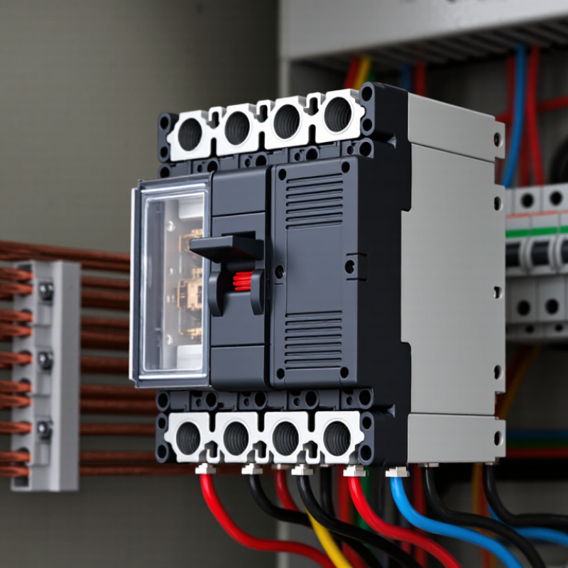
How to Choose a Molded Case Circuit Breaker?

Define System Ratings: Voltage, Current, Frequency, and Fault Current

How to Choose a Molded Case Circuit Breaker?

Define system ratings before comparing breaker frames or accessories. Record the system voltage at the installation point, not only the transformer nameplate. IEC 60947-2 covers low-voltage circuit breakers up to 1,000 V AC and 1,500 V DC. A 480 V system therefore needs a breaker with suitable voltage insulation and switching capability.

Current also requires care. Use the calculated continuous load, conductor ampacity, ambient temperature, and enclosure conditions. A 400 A label may not deliver 400 A in a hot, crowded cabinet. Check the derating tables.

Frequency affects operating performance, especially in systems using motors, generators, or power converters. Confirm whether the supply is 50 Hz, 60 Hz, or variable frequency. The fault-current rating deserves even more attention. IEEE 242 recommends calculating available short-circuit current at the equipment location. NFPA 70 also requires the interrupting rating to meet or exceed available fault current.

Do not guess.

For example, a panel with 35 kA available fault current needs a breaker rated for at least that level under the specified voltage and test conditions. IEC 60909 provides methods for short-circuit calculations in three-phase AC systems. Field measurements can reveal unexpected transformer impedance, utility changes, or parallel generators.

Labels can mislead. Recheck the calculation after major system modifications. That step is often skipped. It should not be.

Compare Icu and Ics: IEC 60947-2 Uses 25–100% Ics of Icu

How to Choose a Molded Case Circuit Breaker?

When selecting a molded case circuit breaker, do not compare only the Icu value. Icu is the ultimate short-circuit breaking capacity under specified voltage, power factor, and test conditions. It shows the highest fault current the breaker can interrupt. However, the breaker may not remain suitable for normal service afterward. In a real panel, that distinction matters.

Ics is the service short-circuit breaking capacity. IEC 60947-2:2016 defines Ics as 25%, 50%, 75%, or 100% of Icu, depending on the tested rating. A breaker with 100 kA Icu and 25% Ics has a service rating of only 25 kA. A 50 kA fault may be interrupted, but continued operation cannot be assumed. The standard’s test framework also checks post-fault performance, including dielectric and operational requirements. See IEC 60947-2:2016, Table 1.

Start with the prospective short-circuit current at the installation point. The IEC Electropedia definitions for Icu and Ics support this comparison. Then check the breaker’s Ics at the actual system voltage, not only the headline rating. A higher Icu can still be the wrong choice. It may offer poor service continuity after a fault. Also review coordination, enclosure temperature, and cable protection. These details are often overlooked. Honestly, Icu alone is not enough. A careful selection compares both values, records the source data, and leaves room for uncertainty in the fault-current calculation.

How to Choose a Molded Case Circuit Breaker? Compare Icu and Ics

According to IEC 60947-2, the service short-circuit breaking capacity (Ics) may be specified as 25%, 50%, 75%, or 100% of the ultimate short-circuit breaking capacity (Icu). Icu is the maximum prospective short-circuit current the circuit breaker can interrupt, while Ics indicates the level at which it can interrupt and remain suitable for continued service. The chart uses a normalized Icu value of 100% to compare the standardized Ics levels; actual current ratings must be selected from the breaker’s technical data and the installation fault level.

Select Poles and Trip Curves for 1–4-Wire Distribution Systems

Choosing a molded case circuit breaker starts with the distribution conductors, not the enclosure size. Count the wires that must be disconnected together. A single-phase line-to-neutral circuit commonly uses one pole, while a line-to-line circuit usually needs two poles. A three-wire split-phase system normally requires a two-pole breaker to open both live conductors simultaneously. In a four-wire, three-phase system, use three poles for the phase conductors. A fourth pole may be suitable when the neutral must also be isolated by the installation design.

Neutral switching needs care. It is not automatically safer. In many systems, the neutral remains solidly connected, while some arrangements require simultaneous neutral disconnection. Confirm the earthing method and local electrical requirements before choosing four poles. A field mistake here can leave unexpected voltage present.

Trip settings should match the load and conductor capacity. Long-time protection should follow the cable’s allowable current, with adjustment for ambient temperature and continuous loading.

Instantaneous pickup must tolerate normal starting current from motors, transformers, or capacitive equipment. Set it too low, and harmless inrush may trip the breaker. Set it too high, and fault clearing may become slower than intended.

Measure actual operating current where possible, then compare it with calculated fault current. Manufacturer data and a qualified review remain important, because molded case breaker trip curves vary by frame and protection unit. I have found that selecting from a familiar application alone can be misleading. The real installation often behaves differently.

Choose Thermal-Magnetic or Electronic Trips for 80% Continuous Loads

How to Choose a Molded Case Circuit Breaker?

For an 80% continuous load, select a breaker that carries the load without operating near its limit. A 100-ampere breaker typically supports up to 80 amperes continuously, unless it is specifically rated for 100% operation. Confirm the rating with the installation code and equipment documentation. In field work, loose terminals and warm enclosures can reduce this margin. That detail is easy to overlook.

Thermal-magnetic trips suit many standard distribution panels. Their thermal element responds to sustained overloads, while the magnetic element reacts quickly to short circuits. They are straightforward, durable, and usually economical. Ambient temperature affects the thermal element, however. A hot electrical room may cause earlier tripping. Check the derating information before choosing one.

Electronic trips provide more precise protection for larger or more critical systems. They can offer adjustable long-time, short-time, instantaneous, and ground-fault settings. This flexibility helps coordinate several breakers and manage continuous loads more accurately. Yet adjustment errors can weaken protection. I have seen settings copied from old drawings without testing the actual circuit. That is not a reliable method. Review the expected load, conductor size, fault current, and coordination study. Then verify the final settings with qualified testing equipment.

How to Choose a Molded Case Circuit Breaker? - Choose Thermal-Magnetic or Electronic Trips for 80% Continuous Loads

Selection Dimension Thermal-Magnetic Trip Electronic Trip Practical Selection Guidance for an 80% Continuous Load
Continuous-load sizing The breaker rating is normally selected so the continuous load does not exceed 80% of the standard breaker's rating, unless the complete equipment is specifically listed for 100% continuous operation. Uses the same continuous-load sizing principle; electronic trip capability does not by itself permit loading a standard breaker above 80% continuously. For a continuous load of 80 A with no other load, the minimum calculated breaker rating is generally 100 A: 80 A × 1.25 = 100 A. Verify the applicable electrical code and equipment listing.
Overload protection A bimetal element responds to heating caused by overcurrent. It normally provides an inverse-time overload characteristic. Current sensors and electronic processing provide adjustable long-time overload protection with more precise pickup settings. Choose thermal-magnetic for straightforward feeder or branch-circuit protection. Consider electronic trip when accurate coordination or adjustable overload protection is important.
Short-circuit protection A magnetic element provides rapid operation during high fault current. The instantaneous pickup is commonly fixed or limited in adjustment. An electronic trip unit provides adjustable short-time and instantaneous functions on models designed with these features. Select the trip type only after confirming the available fault current, required clearing time, and the breaker's interrupting rating at the system voltage.
Typical current range Commonly used across small and medium molded-case breaker applications, with thermal-magnetic designs available from low ampere ratings through large-frame applications. Most often selected for larger frame sizes and higher-current feeders, although electronic trip units are also available in some smaller molded-case frames. Do not select by ampere rating alone. Confirm the specific frame, sensor rating, continuous current rating, and available trip-unit settings.
Adjustability Thermal and magnetic settings are often factory-defined, with limited or no user adjustment depending on the breaker design. Long-time, short-time, and instantaneous settings may be adjustable. Ground-fault protection may also be available on suitable models. Use electronic adjustment only within the manufacturer's permitted range and document the final settings for testing and maintenance.
Selective coordination Coordination is possible but may be limited by fixed trip characteristics and the time-current curves of the upstream and downstream devices. Usually offers more coordination flexibility through adjustable long-time and short-time delays, subject to published coordination data. Prefer electronic trips for critical feeders where only the nearest downstream protective device should operate during a fault.
Temperature effects Thermal response is affected by ambient temperature, enclosure temperature, mounting arrangement, and conductor heating. Electronic sensing is generally less dependent on bimetal heating, but the breaker still requires application-specific derating and thermal evaluation. Check the manufacturer's ambient-temperature adjustment, enclosure conditions, terminal temperature limits, and installation derating requirements.
Power and maintenance Normally operates without an external control power supply. Its simple construction can reduce setup and maintenance requirements. May require sensing power or control power depending on the trip-unit design and available functions. Testing and setting verification are more important. Choose thermal-magnetic where simplicity is the priority; choose electronic where measurement, communications, testing, or coordination justify the added complexity.
Ground-fault protection Generally requires a separate ground-fault protective device or a breaker model specifically designed with that function. Ground-fault sensing and adjustable protection may be integrated into compatible electronic trip units. Confirm whether ground-fault protection is required by the application, system grounding method, and local electrical requirements.
Interrupting rating Available in multiple interrupting ratings; the correct value depends on the system voltage, phase configuration, and tested breaker combination. Also available in multiple interrupting ratings; electronic trip functionality does not replace the need for an adequately rated interrupting device. Select a rating equal to or greater than the calculated available short-circuit current at the installation point, using the applicable test standard.
Voltage and pole configuration Available in one-, two-, three-, and four-pole configurations depending on the system and breaker family. Available in several pole configurations, but electronic accessories and sensing arrangements may limit the available combinations. Verify system voltage, frequency, number of phases, neutral switching requirements, and whether the neutral must be protected or sensed.
Best-fit application General distribution panels, motor feeders where compatible, small commercial installations, and circuits that do not require extensive coordination. Large feeders, critical facilities, high-current distribution, systems requiring coordination, metering, communications, or adjustable protection. For a typical 80%-loaded circuit, thermal-magnetic is usually adequate when fixed protection meets the design. Select electronic when system studies require adjustable or coordinated protection.
Final verification checklist Confirm the calculated continuous and noncontinuous loads; apply the applicable 125% continuous-load factor where required; verify conductor ampacity, breaker rating, voltage, poles, frequency, interrupting rating, enclosure temperature, terminal ratings, available fault current, trip settings, and installation code requirements. A standard breaker is generally not treated as a 100%-rated device unless the complete breaker-and-equipment assembly is specifically listed and installed for 100% continuous operation.

Note: Product availability, trip ranges, interrupting ratings, and 100%-rated continuous-load applications vary by breaker design and applicable standard. Always use the manufacturer's tested data and the electrical requirements governing the installation.

Verify IEC 60947-2 or UL 489 Compliance, Coordination, and Service Life

How to Choose a Molded Case Circuit Breaker?

Start with the installation’s voltage, continuous current, and prospective short-circuit current. The breaker should carry the load without nuisance tripping. It must also interrupt the highest fault current available at its terminals. IEC 60947-2 defines performance tests for industrial low-voltage circuit breakers, including overload and short-circuit duties. UL 489 adds construction and endurance requirements for breakers used in North American applications. Do not treat either marking as decoration. Verify the exact edition, certification scope, and test rating.

Coordination deserves a real study, not a quick catalog check. Compare time-current curves for the main and downstream breakers. A selective arrangement should let the nearest breaker trip first. Check instantaneous settings carefully; two breakers can appear coordinated until a high fault occurs. The International Energy Agency’s Electricity 2024 report projects average global electricity-demand growth of 3.4% annually through 2026. Existing panels may face larger loads sooner than expected. Leave practical capacity, but do not oversize protection casually.

Service life depends on switching frequency, temperature, contamination, and fault exposure. Review the manufacturer’s declared mechanical and electrical endurance, then match it with the site duty cycle. A dusty pump room is not a clean test laboratory. Inspect terminals for heat discoloration and torque loss during planned maintenance. NFPA 70B emphasizes documented electrical maintenance, yet field records are often incomplete. That weakness matters. A breaker may still operate, but its history remains uncertain. Testing assumptions should be written down, challenged, and updated after every major load change.

FAQS

What system details should be checked before choosing a molded case circuit breaker?

Check voltage, continuous load, conductor ampacity, frequency, enclosure temperature, and available fault current. Record conditions at the installation point. Do not rely only on transformer data.

Why does installation voltage matter?

A breaker must match the system voltage for insulation and switching performance. A 480 V system needs suitable ratings at that voltage. Higher headline ratings may still be unsuitable.

How should the current rating be selected?

Use the calculated continuous load and conductor ampacity. Apply derating for ambient heat and crowded enclosures. A 400 A label may deliver less in a hot cabinet.

Does frequency affect breaker selection?

Yes. Confirm whether the supply is 50 Hz, 60 Hz, or variable frequency. Motors, generators, and converters can make frequency especially important.

What is available fault current?

It is the prospective short-circuit current at the equipment location. Calculate it for the actual panel position. Do not guess.

How should the interrupting rating be compared with fault current?

The breaker’s interrupting rating must meet or exceed available fault current. For example, 35 kA available fault current requires at least a suitable 35 kA rating. Voltage and test conditions still matter.

What is the difference between Icu and Ics?

Icu is the ultimate breaking capacity under specified test conditions. Ics is the service breaking capacity. Ics may equal 25%, 50%, 75%, or 100% of Icu.

Why is Ics important after a short circuit?

A breaker may interrupt a high fault under Icu but need service afterward. A breaker with 100 kA Icu and 25 kA Ics may not support continued operation after a 50 kA fault. Icu alone can mislead.

What other checks are easy to overlook?

Review coordination, cable protection, enclosure temperature, and post-fault performance. Recheck calculations after transformer, utility, or generator changes. Labels can mislead.

Conclusion

Choosing the right Molded Case Circuit Breaker starts with clearly defining the electrical system’s requirements, including operating voltage, rated current, frequency, and prospective fault current. These values determine whether the breaker can safely handle normal operation and interrupt abnormal conditions. When comparing breaking capacities, consider both Icu and Ics under IEC 60947-2. Icu represents the ultimate short-circuit breaking capacity, while Ics indicates the service breaking capacity and may range from 25% to 100% of Icu depending on the device.

Next, select the appropriate number of poles for the distribution arrangement, from single-phase systems to three- or four-wire networks, and choose trip characteristics that match the expected load. Thermal-magnetic protection is suitable for many standard applications, while electronic trips offer more precise adjustment for systems with continuous loads approaching 80% of the rating. Finally, verify IEC 60947-2 or UL 489 compliance, proper coordination with upstream and downstream protection, and the breaker’s expected service life before installation.

Eleanor

Eleanor

Eleanor is a dedicated marketing professional with a deep understanding of the company’s products, market trends, and customer needs. Through years of experience in strategic communication, content development, and customer-focused marketing, she helps translate complex product features into clear,......