A lightning flash may last only a moment, but a voltage surge can travel through wiring and damage a control board, router, or refrigerator. A Surge Protective Device (SPD) helps limit that risk. It detects transient overvoltage and redirects excess energy away from connected equipment. In practical terms, it acts like a pressure-release path for electricity—not a shield against every electrical problem.
Electrical engineer and author Thomas A. Short has written extensively about power-system surges. A concise paraphrase of his engineering guidance is: “Effective protection depends on limiting transient voltage where equipment is connected.” This is not a verbatim quotation. The principle is useful because an SPD’s performance depends on its location, ratings, wiring, and coordination with other protective devices. A unit mounted beside a service panel may help protect a building’s electrical system, while a point-of-use device can add protection near sensitive electronics.
The details matter. An SPD may use components such as metal-oxide varistors to conduct surge current when voltage rises above a threshold. Under normal conditions, it remains largely inactive. After repeated surges, however, some components can wear out. Still, no device is magic. Correct selection, installation, and periodic inspection help determine whether protection remains effective. This guide explains the main SPD types, how they respond to surges, and what their ratings can—and cannot—tell you.
What a Surge Protective Device Is
What Is a Surge Protective Device and How Does It Work?
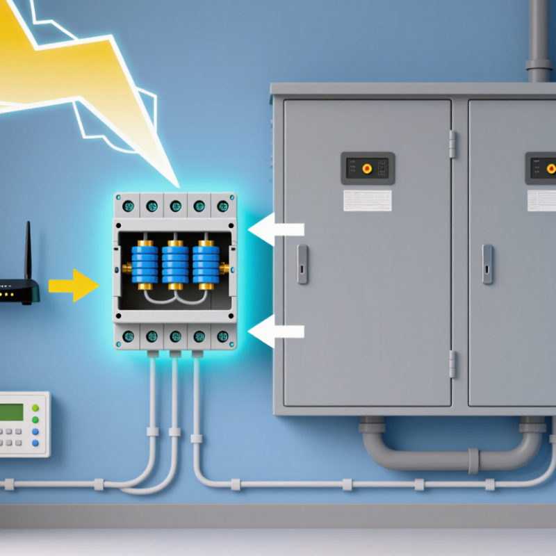
A surge protective device (SPD) is an electrical component that limits brief overvoltages and redirects excess current away from connected equipment. It is commonly installed at a service panel, outlet, or equipment connection. Inside, components such as metal-oxide varistors change their electrical resistance when voltage rises sharply. This gives surge current a safer path, then returns the device to normal operation. That distinction matters. An SPD does not supply backup power or prevent every failure.
Surges can come from utility switching, large motors, or lightning-related events. NOAA’s National Weather Service estimates that about 25 million lightning flashes occur across the United States each year; only some create damaging transients on electrical systems. IEEE Std C62.41.1 describes the surge environment in low-voltage AC circuits, while UL 1449 covers safety and performance requirements for SPDs. These references help explain why selection depends on where the device is installed and the system’s electrical characteristics. A panel-mounted unit may protect circuits broadly, while a point-of-use device adds protection near sensitive electronics. The terminology can be confusing, and one SPD is not a complete protection plan. Grounding, wiring condition, and correct installation still matter.
What Is a Surge Protective Device and How Does It Work? – What a Surge Protective Device Is
| Dimension | What It Means | How It Works or Is Used |
|---|---|---|
| Definition | A surge protective device (SPD) is equipment designed to limit transient overvoltage and divert surge current. | It helps reduce the surge voltage reaching connected electrical equipment; it does not regulate normal voltage or protect against every electrical fault. |
| Common surge sources | Lightning-induced surges, utility switching, and switching of inductive loads can create brief voltage transients. | An SPD provides a controlled path for surge current, typically between live conductors and ground or between conductors, depending on its configuration. |
| Basic operating principle | The device changes its electrical behavior when voltage rises above its operating threshold. | It becomes conductive during a transient, diverts surge current, and limits the voltage at its terminals. It returns to its normal high-impedance state when the transient ends, if it remains serviceable. |
| Metal-oxide varistor (MOV) | A voltage-dependent component commonly used in many AC power SPDs. | Its resistance drops sharply as voltage rises, allowing surge current to flow. Repeated or severe surges can degrade an MOV over time. |
| Gas discharge tube (GDT) | A gas-filled component used in some surge protection designs. | When its sparkover voltage is reached, the gas becomes conductive and can carry surge current. Its response and follow-current behavior differ from those of an MOV. |
| Transient-voltage-suppression diode (TVS) | A semiconductor component often used for lower-voltage or signal-circuit protection. | It responds rapidly to transient overvoltage and clamps the voltage within limits set by its design and circuit conditions. |
| Type 1 SPD | A classification used for SPDs installed at or near the service entrance, where specified by the applicable electrical standard. | Type 1 devices are tested for impulse current performance. Installation requirements depend on the local code and system arrangement. |
| Type 2 SPD | A classification commonly used for SPDs installed in a distribution panel. | Type 2 devices are evaluated for discharge-current performance, including nominal discharge current (In); some specifications also state maximum discharge current (Imax). |
| Type 3 SPD | A classification for point-of-use protection installed close to the equipment being protected. | Type 3 devices are generally used as part of a coordinated protection arrangement and are evaluated using a combination-wave test, often stated as open-circuit voltage (Uoc). |
| Voltage protection level (Up) | A rated value describing the voltage-limiting performance of an SPD under specified test conditions. | When selecting an SPD, compare its Up with the withstand capability of the equipment and follow the requirements of the applicable standard. |
| Maximum continuous operating voltage (Uc) | The maximum RMS voltage that may be applied continuously to the SPD’s designated terminals under specified conditions. | Uc must suit the electrical system. An unsuitable value can result in inadequate protection or unwanted operation. |
| End-of-life indication | SPDs can wear out or become disconnected after repeated or unusually severe surges. | Many designs include a status indicator or require an external protective device. Follow the manufacturer’s instructions and replace a device that signals it is no longer operational. |
| Installation and coordination | Protection depends on correct device selection, wiring, earthing, and installation. | Short, appropriately routed connecting conductors help limit additional voltage during a surge. Installation should comply with local electrical codes and be performed by a qualified person. |
| Protection limits | An SPD is one part of an electrical protection strategy, not a guarantee against all damage. | Its performance depends on the surge, wiring, grounding, device condition, and coordination with other protection. It does not replace overcurrent protection or a lightning protection system where one is required. |
Note: SPD classifications, test values, and installation rules vary by electrical system and applicable standard. Always check the device rating and local requirements before installation.
FAQS
It limits brief voltage surges by giving excess current a lower-impedance route. It does not erase every surge.
At normal voltage, it has high resistance. As voltage rises, its resistance drops, allowing more current to pass.
Yes. Repeated surges can wear down the varistor over time. Its protection may become depleted.
It separates an overheated varistor from the circuit and helps reduce fire risk. Not every design uses identical parts.
No. A status window can show depleted protection, but it may not reveal every fault.
Depending on the installation, it may flow toward the grounding and bonding system. The device also limits voltage across connected equipment.
Long or loose wiring can weaken protection. A long grounding lead may leave more voltage at equipment than expected.
Check its status indicator during routine inspections. A lit indicator is not a guarantee, and that detail is easy to underestimate.
Conclusion
A Surge Protective Device (SPD) helps protect electrical systems and connected equipment from sudden increases in voltage, known as surges. Inside an SPD, components such as voltage-sensitive elements and protective connections monitor the electrical supply. When voltage rises above a safe level, the device responds by providing a controlled path for excess energy to flow away from sensitive circuits, then returns to its normal monitoring state.
SPDs come in different types for use at service entrances, distribution panels, or near individual devices, depending on the level and location of protection needed. They may be installed in residential, commercial, or industrial electrical systems. Choosing an SPD involves considering the system voltage, expected surge conditions, installation location, protection rating, and compatibility with the equipment. Proper selection and installation help provide coordinated protection throughout an electrical system.