Featured Protection, Timing & Intelligent Current Sensing Hardware
Precision-matched switching relays, DIN-rail energy monitors, and custom flexible OEM sensor suites engineered under stringent TÜV Rheinland-assessed manufacturing tolerances.
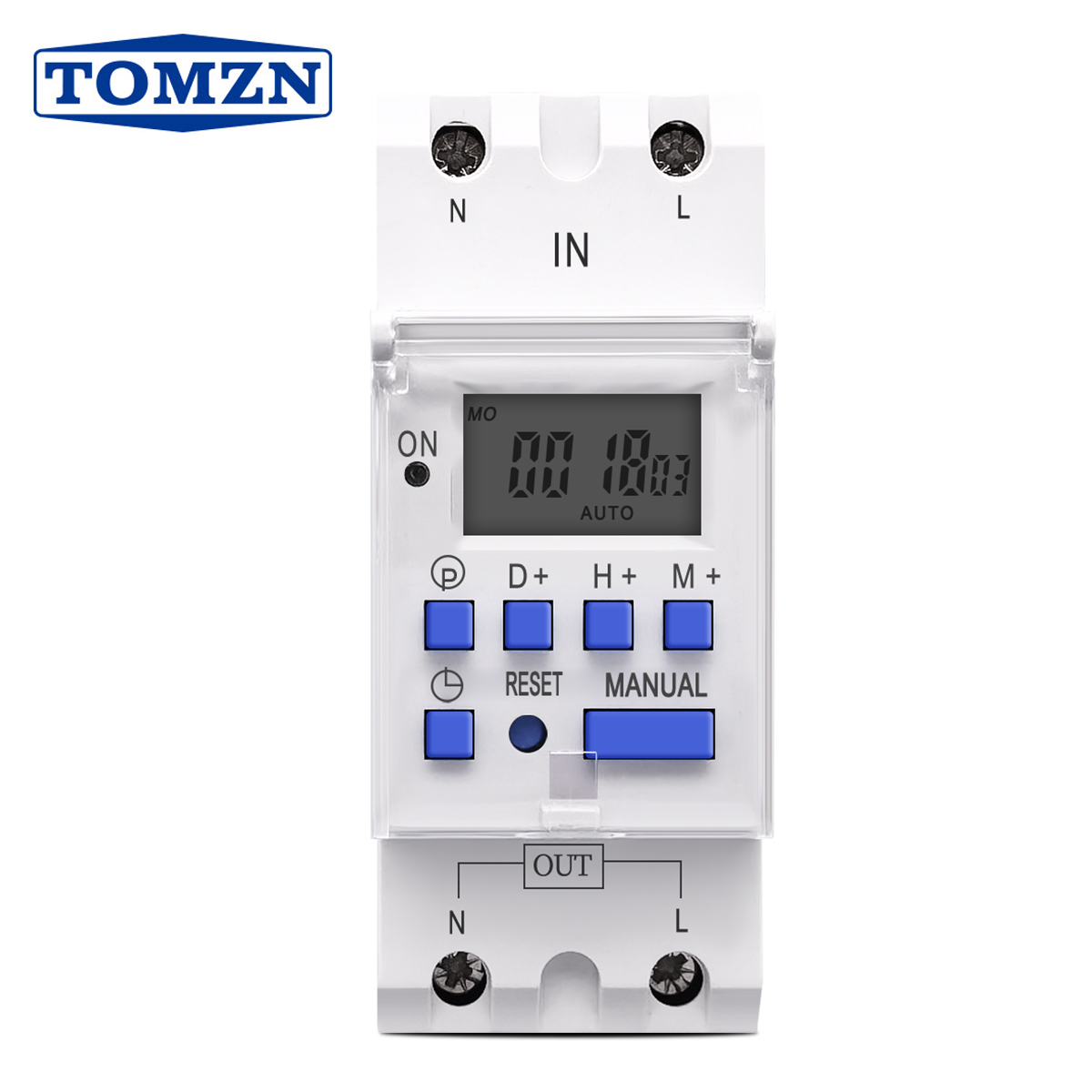
TOMZN Single Phase Weekly 7 Days Programmable Digital Time Switch AC 220V/230V 12V 24V 48V 16A
View Specifications →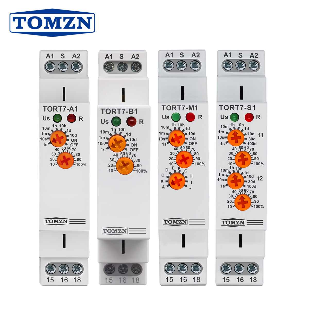
TORT7 Series Delay-ON Delay-OFF 10in1 Asymmetric Cycler Multi-function Time Relay Pulse Interval Switch
View Specifications →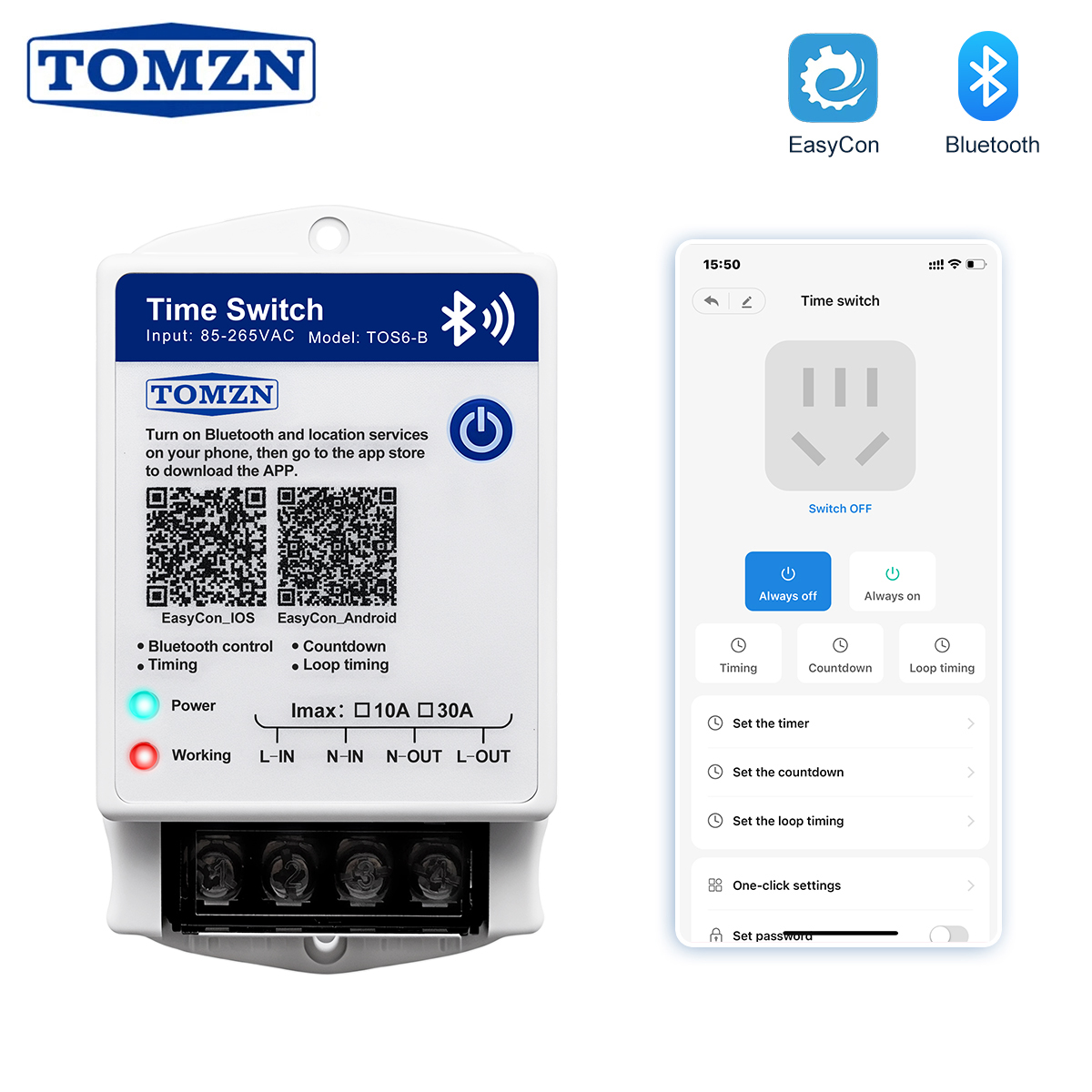
TOMZN Bluetooth Smart Timer Switch 85-265VAC 10A 30A EasyCon Wall-Mounted Loop Countdown Controller
View Specifications →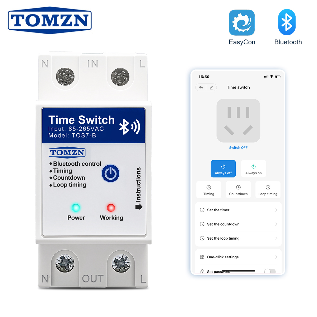
TOMZN TOS7-B Bluetooth Smart High-Current Switch 40A 63A 85-265V App Scheduled Automated Controller
View Specifications →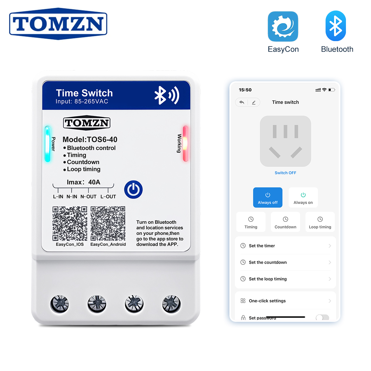
TOS6-40 Bluetooth Time Control Switch 35mm DIN Rail Wall-Mounted Infinite Loop Programmable Relay
View Specifications →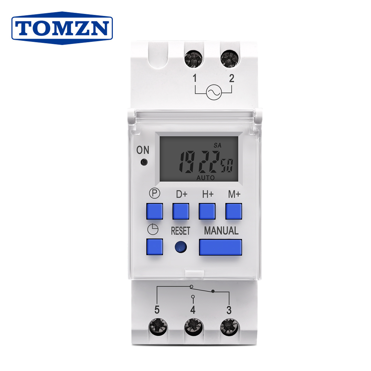
TOMZN 1NO 1NC DIN Rail Single Phase Weekly 7 Days Multi-Voltage Programmable Digital Time Switch Relay
View Specifications →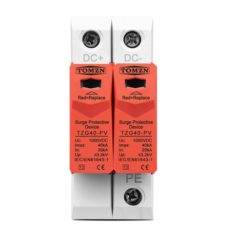
Custom OEM Flexible Rogowski Coil Current Sensor with Calibrated Analog/Digital Integrator Circuitry
Get a Quote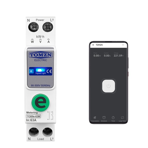
Integrated DIN-Rail Multi-Channel Energy Hub with Rogowski Sensor Inputs & Dynamic Load Analytics
Get a QuotePrecision Rogowski Coil Technology: Physics, Integrator Design & Industrial Metrology
As modern power electronics transition aggressively toward high-power-density wide-bandgap (WBG) semiconductors like Silicon Carbide (SiC) MOSFETs and Gallium Nitride (GaN) HEMTs, traditional ferromagnetic iron-core current transformers (CTs) face fundamental physical barriers. Conventional current transducers suffer from magnetic core saturation under high transient surges, catastrophic non-linear hysteresis, limited frequency response bandwidth, and bulky physical form factors that fail to fit inside tight switchgear assemblies.
A precision-engineered Rogowski coil current sensor solves these critical constraints by utilizing a coreless toroidal solenoid wound uniformly around a non-magnetic former (μr = 1). Because the magnetic core is eliminated, the sensor exhibits complete immunity to DC saturation, exceptional linearity from fractions of an ampere up to mega-ampere thresholds, and unmatched high-speed transient di/dt tracking capabilities.
1. Fundamental Electrodynamics and Mutual Inductance Theory
The operating mechanism of an alternating current Rogowski coil is governed by Faraday's Law of Electromagnetic Induction. When an alternating primary conductor carrying current i(t) passes through the enclosed aperture of the coil, it induces a time-varying magnetic flux across the winding cross-section. The induced open-circuit voltage e(t) at the sensor output terminals is strictly proportional to the time rate of change of the primary current:
e(t) = -M · [di(t) / dt]
Here, M denotes the mutual inductance between the primary conductor and the closed secondary winding loop. For an ideally wound toroid of uniform cross-sectional area A with turn density n (turns per unit length), the mutual inductance is defined by:
M = μ0 · n · A = μ0 · (N / 2πr) · A
In real-world industrial installations, maintaining positional invariance—ensuring the output voltage remains constant regardless of whether the conductor sits dead-center or near the loop periphery—requires extraordinary winding precision. At our Liushi manufacturing base, automated multi-axis winding machinery guarantees pitch-uniformity down to microscopic tolerances, mitigating positional offset error to below ±0.5% across the entire active sensor aperture.
2. Electronic Signal Conditioning: Active vs. Passive Integrator Architectures
Because the raw output voltage of the Rogowski sensor represents the differential derivative di(t)/dt rather than the instantaneous current waveform itself, an electronic integrator stage is essential to restore the true phase and amplitude profile of the measured current. Choosing the appropriate integrator topology directly dictates dynamic range, signal-to-noise ratio (SNR), and operational bandwidth:
Active Analog Integrators
Utilizing low-drift, wide-gain-bandwidth operational amplifiers in conjunction with high-stability metal film feedback resistors and low-leakage polyphenylene sulfide (PPS) capacitors. Delivers flat frequency response from 0.5 Hz up to 1 MHz with minimum phase error (< 0.1° at 50/60 Hz grid frequencies).
Digital DSP / FPGA Integrators
Digitizes the raw di/dt voltage signal directly via high-speed 24-bit delta-sigma (ΔΣ) ADCs, executing numerical integration algorithms within discrete firmware. Provides exceptional long-term drift stability, automated offset cancellation, and direct interface to IEC 61850-9-2 process bus sampled values.
Passive Low-Pass Networks
A cost-effective, self-powered RC filter network functioning as an integrator at frequencies significantly higher than its corner frequency (ω >> 1/RC). Best suited for high-frequency short-circuit fault sensing and lightning discharge pulse monitoring where external auxiliary power supplies are absent.
3. Comprehensive Metrological Comparison: Rogowski vs. Traditional CTs
| Performance Vector | OEM Precision Rogowski Coil Sensor | Conventional Iron-Core CT (5A / 1A) | Hall Effect Current Sensor (Closed Loop) |
|---|---|---|---|
| Saturation Characteristic | Zero Magnetic Saturation (Coreless Air Former) | Saturates under Overcurrent / DC Offsets | Susceptible to Core Magnetization Drift |
| Dynamic Measurement Span | Ultra-wide: 1 A up to 100,000 A with single coil | Narrow: Typ. 1% to 120% of rated nominal current | Moderate: Typically 0 to 3x nominal range |
| Physical Safety & Open-Circuit Risk | Inherently Safe: Millivolt-level output; no lethal arcs | Extremely Dangerous: Fatal high-voltage inductive arcing | Safe: Low-voltage secondary circuitry |
| Frequency Bandwidth | Broadband: 0.1 Hz to 20 MHz (Coil-dependent) | Severely Limited: 45 Hz to 400 Hz typical | DC to 200 kHz |
| Mechanical Flexibility & Installation | Ultra-flexible rope design; zero busbar interruption | Rigid, heavy steel laminations; difficult retrofits | Rigid through-hole; requires physical conductor disconnection |
| Linearity Error (IEC 61869-10) | Class 0.2 / Class 0.5S achievable across wide envelope | Degrades rapidly below 5% or above 120% rating | Class 0.5 to Class 1.0; subject to thermal offset |
Future Procurement Dynamics: Why Global EPCs & OEMs Are Shifting to Rogowski Systems
The global transition toward decentralized clean energy grids, megawatt-scale solar PV installations, industrial battery energy storage systems (BESS), and hyperscale data center submetering has altered the technical criteria for purchasing instrument transformers. Global sourcing directors and supply chain managers are shifting focus away from commoditized legacy split-core CTs toward modular, flexible Rogowski sensor architectures for four distinct operational reasons:
1. Retrofit Labor Cost Compression
Eliminating downtime on commercial distribution boards saves thousands of dollars per feeder. Flexible snap-together Rogowski coils loop around irregular busbars and thick cable bundles without disconnecting main supply lines.
2. Inventory SKU Consolidation
Instead of stocking dozens of discrete CT ratios (e.g., 100/5A, 250/5A, 800/5A, 2500/5A), procurement departments standardize on a single universal Rogowski coil length paired with a field-configurable multi-range integrator.
3. International Grid Compliance
Adherence to the modern IEC 61869-10 standard (Low-Power Instrument Transformers / LPIT) has made small-signal outputs standard across state-of-the-art digital power meters, eliminating bulky internal shunt resistors.
4. Extreme Space Constraints
Modern electrical enclosures and PV combiner boxes demand compact DIN-rail density. Rogowski coils measure high currents with an outer loop profile under 8mm in diameter, fitting into spaces where iron-core CTs cannot.
Furthermore, in solar photovoltaic combiner boxes and dual power automatic transfer switch (ATS) installations, transient harmonics caused by switching inverters can easily drive standard iron cores into premature thermal breakdown. By specifying air-core Rogowski coils with certified dielectric jackets (rated for CAT III 1000V / CAT IV 600V), system integrators ensure decades of maintenance-free service across harsh ambient operating temperatures ranging from -40°C to +85°C.
Technological Evolution: Next-Generation Rogowski Coil Innovation
The market for current transducers is moving beyond simple copper wound coils toward intelligent, digitally compensated sensing subsystems. As an innovative manufacturer rooted in the Liushi electrical cluster, Zhejiang TMB Electric monitors and pioneers several evolutionary trajectories:
PCB-Embedded Micro-Rogowski Arrays
By executing Rogowski coils via multi-layer high-density PCB geometries with blind-via interconnects, manufacturing tolerances achieve sub-micron precision. This design is ideal for direct mounting around SiC power module terminals to capture lightning-fast switching transients up to 50 MHz.
Temperature-Compensated DSP Algorithms
While Rogowski former materials are selected for ultra-low thermal expansion coefficients, integrator operational amplifiers still introduce minute thermal drift. Next-generation smart coils incorporate embedded temperature sensors that dynamically calculate real-time polynomial gain corrections.
Direct Optical & Wireless Bus Integration
Future sensor suites eliminate conventional copper secondary leads entirely. By situating ultra-low-power micro-integrators directly inside the coil joint connector, output current data is transmitted wirelessly via Bluetooth Low Energy or optically via noise-immune fiber optic lines directly to industrial controllers.
Zhejiang TMB Electric Co., Ltd. — Your Dependable OEM / ODM Partner
Situated in Huabei Village, Liushi Town, Wenzhou—widely recognized as China's premier low-voltage electrical apparatus cluster—Zhejiang TMB Electric Co., Ltd. brings over 24 years of manufacturing heritage to tier-1 global distributors, panel builders, and renewable energy EPC contractors. Our comprehensive infrastructure empowers international B2B clients with distinct structural benefits:
Full Cluster Supply Chain Control
Our localized proximity to high-purity electrolytic copper drawing facilities, specialized silicone extrusion plants, and flame-retardant tooling centers ensures rapid sampling, minimized bill-of-materials costs, and agile supply-chain elasticity.
TÜV Rheinland Audited Quality
Our 5,700 m² manufacturing plant and 92 skilled personnel have undergone rigorous on-site verification by TÜV Rheinland. We enforce standard ISO 9001 procedures across every incoming material check, coil winding cycle, and final dielectric burn-in phase.
Bespoke OEM/ODM Customization
Whether you require customized loop circumferences (100mm to 2000mm+), specialized integrators outputting 0-5V / 4-20mA / 333mV / 100mV, custom color jackets, or private-label laser etching, we provide end-to-end turn-key development starting from 5 pcs trial MOQ.
Engineering Trust Across 100+ Global Markets
Backed by over US$ 3.3M in audited annual export volume, Zhejiang TMB Electric supports high-profile projects ranging from solar combiner box assemblies and dual power ATS integration to commercial energy monitoring systems. We supply complete test certificates, CE declarations, and technical datasheets before dispatch.
Frequently Asked Questions for Rogowski Coil & Electrical Sourcing
Critical engineering considerations, wiring practices, and commercial policies compiled by our technical sales specialists for overseas electrical engineers and purchasing managers.
What are the key technical specifications required to quote a custom OEM Rogowski coil?
To deliver an exact technical proposal and quotation, our engineering team requires: (1) Primary current range: Nominal continuous operating current and expected peak short-circuit current; (2) Desired sensor inner diameter / length: Standard loop diameters range from 50mm, 100mm, 150mm to 300mm+; (3) Desired secondary output signal: Direct millivolt di/dt output (e.g., 50mV/1000A @ 50Hz) or conditioned output via an integrator (e.g., 0-5V AC, 333mV AC, 4-20mA DC, or 1A AC equivalent); (4) Auxiliary power supply availability: e.g., ±12V DC, 24V DC, or loop-powered; (5) Accuracy class: e.g., 0.5% or 1.0% per IEC 61869-10; and (6) Lead wire length and connector interface.
Can a Rogowski coil measure direct current (DC) components in power networks?
A standard Rogowski coil operates purely on electromagnetic induction via the derivative di/dt; therefore, it produces zero steady-state output when exposed to continuous, unvarying DC currents. However, its completely non-magnetic air core means it will never saturate even when an enormous DC bias current is superimposed onto an alternating AC signal. This distinct advantage makes Rogowski coils uniquely qualified for measuring AC ripples and harmonic distortion in EV fast chargers, solar PV inverters, and battery storage systems where traditional CTs would experience severe core saturation and burn out.
How does conductor positioning inside the coil aperture impact measurement accuracy?
According to Ampère's circuital law, a closed line integral around a current conductor is theoretically independent of conductor position. However, in physical coils, slight pitch variations during winding and gaps at the mechanical latch closure can introduce localized sensitivity discrepancies. At Zhejiang TMB Electric, we use specialized continuous return windings threaded directly through the center of the solenoid before external insulation shielding is applied. This design neutralizes external field interference and restricts positional error to less than ±0.5% anywhere within the coil loop.
Why is an open secondary Rogowski coil fundamentally safer than an iron-core CT?
When the secondary circuit of an energized conventional iron-core CT (e.g., 1000/5A) is accidentally opened, the absence of opposing secondary ampere-turns forces all primary current to become magnetizing current. This drives the iron core into intense saturation, generating dangerous induced peak voltages (often exceeding 2,000 to 5,000 Volts) across secondary terminals, which can cause fatal electric shocks and catastrophic explosive flashovers. In contrast, a Rogowski coil has an air core with very low mutual inductance; its open-circuit output voltage is physically constrained to harmless millivolts or low volts even during mega-ampere short-circuit transients, safeguarding installation personnel and switchgear instrumentation.
What are your factory lead times, MOQ policies, and warranty terms for OEM orders?
We provide sample prototypes and standard catalog units from an accessible MOQ of 5 pieces (and selected timer switches from 1 piece) to allow comprehensive validation before large rollouts. Standard custom prototype lead times are typically 7 to 10 working days, while full container-load production orders are completed within 20 to 28 days. Every unit undergoes 100% automated dielectric and functional calibration before dispatch and is backed by our standard 18-month manufacturing warranty with full technical traceability.
Looking to Upgrade Your Current Sensing or Power Protection Hardware?
Share your single-line diagram, technical specifications, and target quantities with our engineering team in Liushi, Wenzhou. We provide rapid technical review, complimentary datasheets, and direct factory-gate pricing within 24 business hours.