Precision Motor Control & Intelligent Electrical Switching Systems
Direct-from-factory solutions engineered for high duty cycles, extreme thermal stability, and seamless DIN-rail cabinet integration. Each unit undergoes strict multi-stage dielectric, functional, and trip calibration.
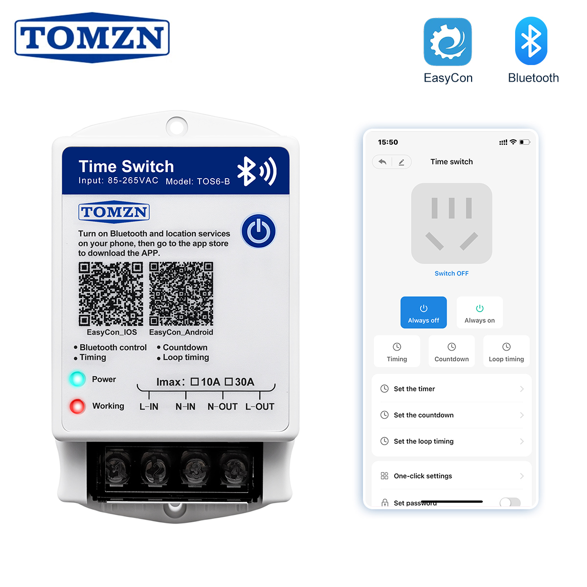
TOMZN Bluetooth Smart Timer Switch 85-265VAC 10A 30A EasyCon Wall-mounted Countdown
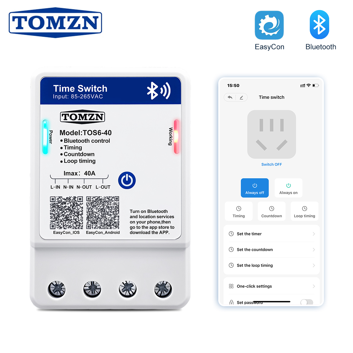
TOS6-40 Bluetooth Time Control Switch 35mm DIN Rail Wall-mounted 40A
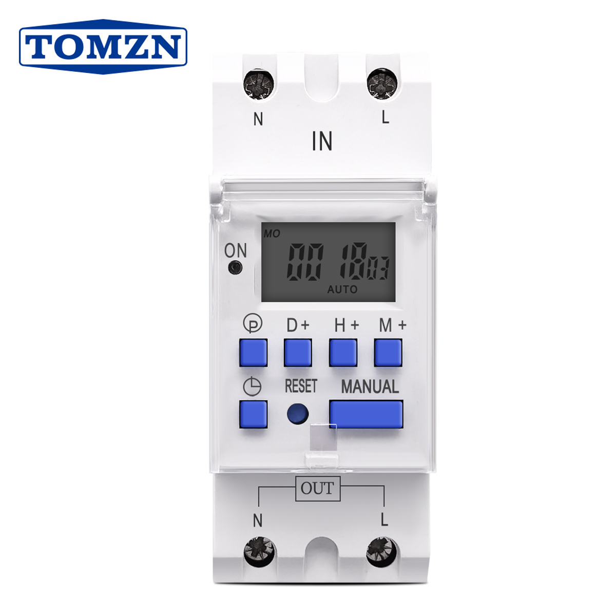
TOMZN New Type Din Rail Single Phase Weekly 7 Days Programmable Timer Switch
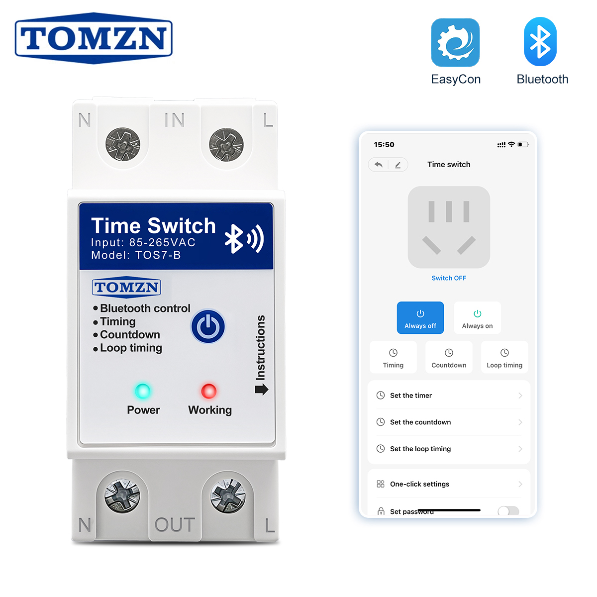
TOMZN TOS7-B Bluetooth Smart Timer Switch 40A 63A 85-265V EasyCon Remote Control
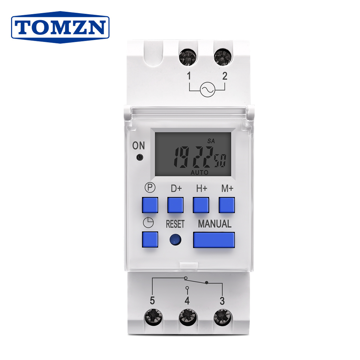
TOMZN 1NO 1NC Din Rail Single Phase Weekly 7 Days Digital Relay Timer Switch
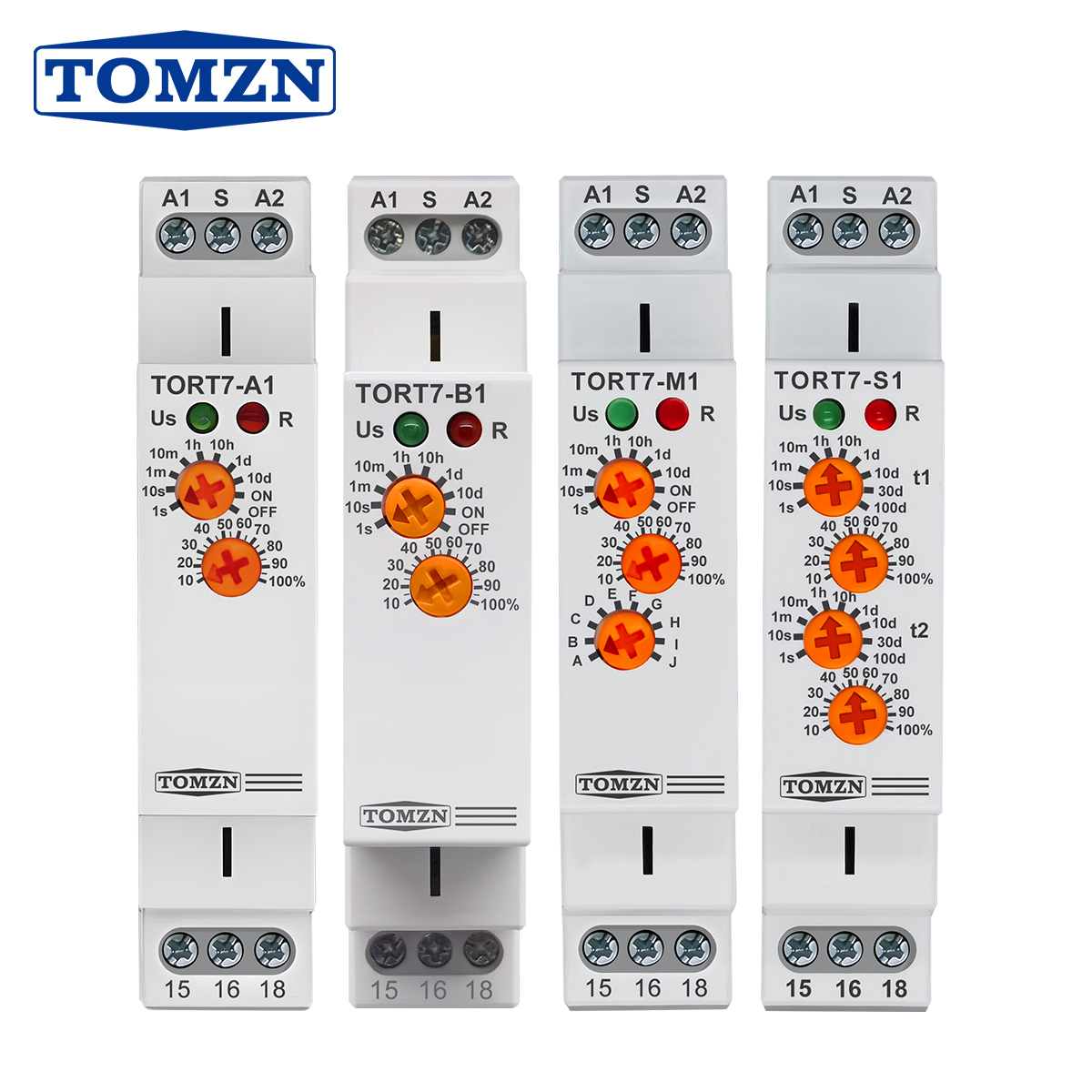
TORT7 Series Delay-ON Delay-OFF 10in1 Asymmetric Cycler Multi-function Timer Relay
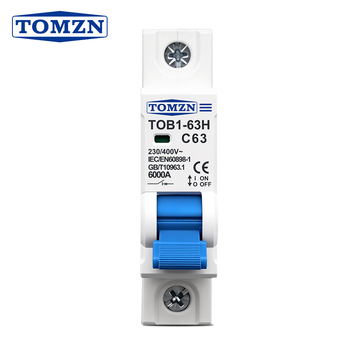
TOB1-63H Industrial AC MCB Overcurrent & Short-Circuit Protection Breaker
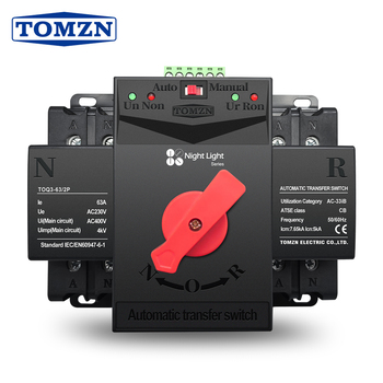
TOQ3 2P Industrial Dual Power Automatic Transfer Switch (ATS) 63A-125A
Industrial Frequency Inverter Topologies & Control Vector Dynamics
A rigorous examination of modern variable frequency drive (VFD) engineering, switching modulation, flux orientation, and thermal survivability in demanding factory environments.
In modern industrial manufacturing, three-phase asynchronous motors and permanent magnet synchronous motors (PMSM) consume upwards of 65% of all factory electrical energy. As heavy industries—including chemical processing, metal forming, CNC machining, wastewater treatment, and mining—accelerate toward electrification and smart automation, the role of the Industrial Frequency Inverter (Variable Frequency Drive / VFD) has evolved beyond rudimentary open-loop speed variation. Contemporary OEM/ODM frequency inverters represent complex cyber-physical power electronics suites that simultaneously govern magnetic torque dynamics, minimize mechanical shock, mitigate electrical harmonic pollution, and feed diagnostic parameters into decentralized Industrial Internet of Things (IIoT) control buses.
At the silicon junction level, state-of-the-art frequency inverters utilize Insulated Gate Bipolar Transistor (IGBT) matrices switched via advanced Sinusoidal Pulse-Width Modulation (SPWM) or Space Vector Pulse-Width Modulation (SVPWM). SVPWM treats the inverter bridge as a single unit, generating an optimal circular rotating flux vector that extracts up to 15% higher fundamental output voltage compared to conventional carrier-based SPWM while dramatically reducing current ripple and acoustic motor resonance. The mathematical foundation transitions between three distinct control paradigms:
| Inverter Topology / Control Mode | Dynamic Speed Response | Torque Accuracy at Low RPM (0.5 Hz) | Hardware Computational Overhead | Typical Industrial Applications |
|---|---|---|---|---|
| Scalar V/Hz Control (Open Loop) | Slow (100–150 ms) | Low (Voltage boost required; prone to stall) | Minimal (8-bit or low-cost 32-bit MCU) | Centrifugal HVAC fans, low-head wastewater pumps, single conveyors |
| Sensorless Vector Control (SVC) | Moderate to Fast (10–20 ms) | High (150% rated torque at 0.5 Hz) | Moderate (32-bit ARM Cortex-M4 / DSP) | Industrial extruders, commercial mixers, heavy machine tool spindles |
| Closed-Loop FOC (Field Oriented) | Ultra-Fast (<5 ms) | Exceptional (200% holding torque at 0 Hz) | Extensive (Dedicated Dual-Core DSP + CPLD/FPGA) | High-speed automated hoisting, CNC multi-axis synchronization, winding reels |
| Direct Torque Control (DTC) | Instantaneous (<2 ms) | High (Hysteresis-based instantaneous flux) | Very High (High-sampling A/D converters & lookup tables) | Mine winders, continuous rolling mills, heavy paper machine drives |
Critical Engineering Parameter: Inverter Output dv/dt & Reflected Wave Phenomena
When high-frequency IGBTs switch at rates between 4 kHz and 16 kHz with ultra-fast rise times (tr < 0.1 µs), steep voltage fronts travel down the motor feeder cables. When long feeder distances exceed critical lengths (typically >30 meters), impedance mismatches cause transmission-line reflected wave spikes that double the peak terminal voltage (reaching 1,200V–1,600V on a 400V mains). Without integrated output dV/dt filters, reactor chokes, or high-grade turn-to-turn phase insulation, premature dielectric breakdown of the motor windings occurs. TMB Electric's OEM/ODM inverter designs accommodate both internal line-load reactors and custom magnetic core snubbers to fully suppress destructive peak voltage wavefronts.
Why Global B2B Brands Partner with Zhejiang TMB Electric
Situated in Huabei Village, Liushi Town, Wenzhou—the globally renowned epicenter of China's electrical apparatus manufacturing—Zhejiang TMB Electric Co., Ltd. blends 24 years of electrical engineering excellence with comprehensive OEM/ODM supply chain agility.
Liushi Supply Chain Cluster
Our 5,700 m² advanced facility is embedded in Liushi, Wenzhou, granting instantaneous access to localized raw materials: electrolytic copper busbars, precision silver alloy contacts, ultra-pure magnetic silicon steels, and engineering polymers within minutes, ensuring rapid tooling iterations and minimal production lead times.
TÜV Rheinland On-Site Verification
Trust is cemented through rigorous external oversight. Zhejiang TMB Electric's production facilities, assembly lines, employee safety regimes, and Quality Management Systems (QMS) are independently assessed and certified on-site by TÜV Rheinland, backed by verified annual export figures exceeding US$ 3.3 Million.
Complete OEM/ODM Customization
From custom IGBT thermal dissipation heatsinks and modified terminal blocks to bespoke control firmware algorithms (specialized PID loops, multi-pump cascading logic, Modbus/CANopen communications), we tailor every dimension of the drive and peripheral enclosure to your target market specifications.
CE Compliance & Rigorous QA
Every product model carries full CE conformity, passing through computerized dielectric isolation testing (up to 2,500V AC withstand), high-temperature environmental burn-in stress screening, and automated oscilloscope wave-shape analysis to eliminate infant mortality defects.
Rapid Prototyping & Low MOQ
We break barriers for industrial EPCs and growing private label distributors by providing low trial Minimum Order Quantities (MOQs as low as 1 to 5 pieces on standard catalogue items) alongside lightning-fast engineering prototype delivery within 7 to 14 days.
Comprehensive Distribution Subsystems
Unlike singular VFD assemblers, TMB manufactures the entire DIN-rail protection ecosystem: DC/AC miniature circuit breakers, dual power automatic transfer switches (ATS), modular contactors, lightning surge arresters (SPD), and intelligent programmable time relays.
Standardized Production & Advanced Quality Control Protocols
Spanning 5,700 m² of specialized manufacturing floor space in Huabei Village, Liushi Town, our plant operates automated SMT surface-mount lines, wave soldering machines, and dedicated robotic assembly benches. Every device that leaves our floor is serialized and subjected to uncompromising quality inspections.
For industrial frequency control systems and auxiliary protection gear, our test benches execute dynamic thermal cycling under 100% nominal electrical load, transient impulse testing up to 6 kV, and micro-ohmmeter contact resistance verifications. By integrating our manufacturing base with Liushi's comprehensive raw component logistics, we eliminate overseas supply bottlenecks and deliver verifiable, enterprise-grade reliability.
Future Sourcing & Technological Trends in Frequency Inverters (2025–2030)
Strategic engineering analysis designed to inform industrial procurement directors, automation panel integrators, and OEM equipment manufacturers navigating the evolving drives ecosystem.
1. Wide Bandgap (SiC & GaN) Integration
Silicon Carbide (SiC) and Gallium Nitride (GaN) power MOSFETs are aggressively supplanting conventional silicon IGBTs in high-performance inverters. Offering 10x higher dielectric breakdown fields and 3x higher thermal conductivity, SiC devices cut switching losses by over 70%, permitting switching frequencies above 50 kHz. This slashes cooling heatsink volumes by 50% and dramatically shrinks physical cabinet footprints.
2. Edge AI & Sensorless Predictive Health
Procurement teams are shifting away from dumb inverters toward smart edge-computing drives. Modern DSPs run micro-neural networks directly on current and voltage phase measurements, detecting winding insulation degradation, motor bearing micro-pitting, and mechanical load anomalies prior to catastrophic line shutdowns without requiring external vibration sensors.
3. Active Front End (AFE) Clean Power
With global electrical authorities enforcing stringent harmonic standards (such as IEEE 519-2022), traditional 6-pulse diode bridge rectifiers are being replaced by Active Front End (AFE) bidirectional IGBT rectifiers. AFE drives achieve near-unity power factor (cos phi > 0.99), reduce Total Harmonic Current Distortion (THDi) to under 5%, and regenerate kinetic braking energy directly back into the AC supply grid.
4. Decentralized & Direct-PV Solar Hybridization
The convergence of renewable energy and industrial pumping/ventilation has fueled exponential demand for hybrid VFDs. Modern inverters accept direct DC solar string inputs (up to 1,000V DC) alongside standard grid AC, running integrated Maximum Power Point Tracking (MPPT) algorithms to seamlessly blend solar power with utility power, drastically cutting operational diesel or grid consumption.
5. Integrated Functional Safety (SIL3 / PL e)
External safety contactor panels are being superseded by built-in functional safety architectures. Modern OEM/ODM procurement contracts mandate integrated Safe Torque Off (STO), Safe Stop 1 (SS1), and Safely-Limited Speed (SLS) conforming to IEC 61800-5-2 and ISO 13849-1 standards, simplifying electrical cabinet schematics and lowering bill-of-materials costs.
6. Advanced Harsh Environment Coatings (Class 3C3)
With industrial automation expanding in coastal chemical plants, wastewater digestion facilities, and heavy mining installations, resistance to hydrogen sulfide (H2S), chlorine, and ammonia vapors is vital. Drive exporters must provide conformal PCB coatings certified to IEC 60721-3-3 Class 3C3 and Class 3S3, guaranteeing 100,000 hours of continuous MTBF under corrosive atmospheric exposure.
Frequently Asked Questions on Frequency Inverters & Electrical Procurement
Detailed engineering and supply chain solutions answering the critical parameters evaluated by EPC contractors, panel builders, and import procurement managers.
What are the key technical parameters required when sizing an industrial frequency inverter?
How does Zhejiang TMB Electric handle customized OEM/ODM hardware and software firmware requests?
Why is dynamic braking resistance critical, and how is it calculated for decelerating loads?
What are the differences between Open-Loop V/f Control and Closed-Loop Field Oriented Vector Control (FOC)?
What certifications and verification reports accompany export shipments from Zhejiang TMB Electric?
How does motor cable distance impact inverter operation, and when must line reactors be specified?
Accelerate Your Automation Projects with a Direct Manufacturer
Consult with our senior electrical engineers to match motor dynamics, review single-line schematics, request custom OEM/ODM production schedules, or receive immediate factory quotations.